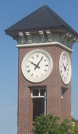
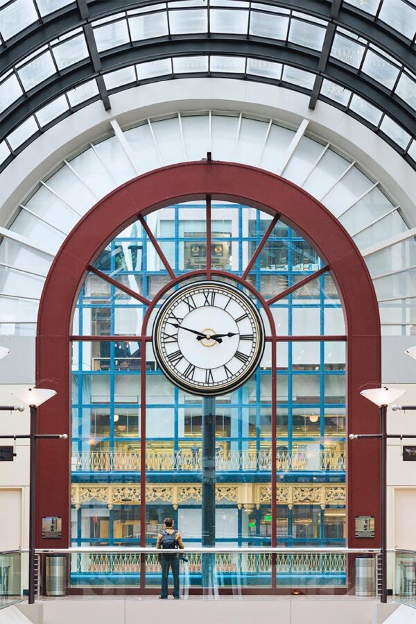
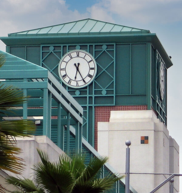
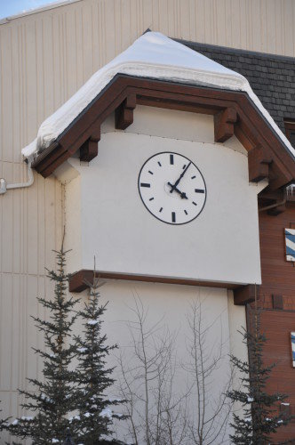
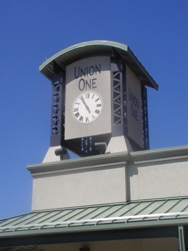
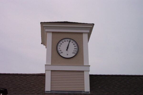
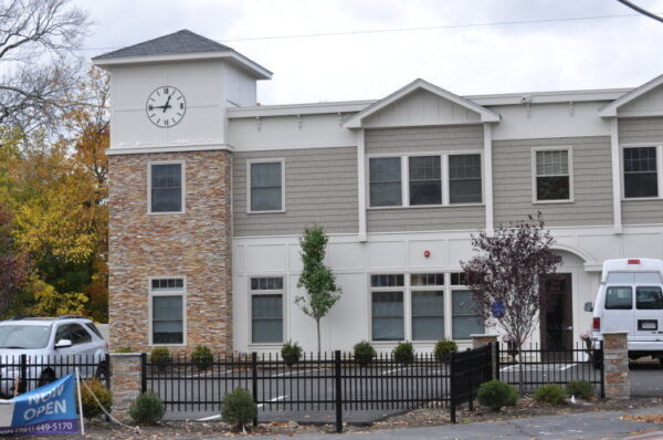
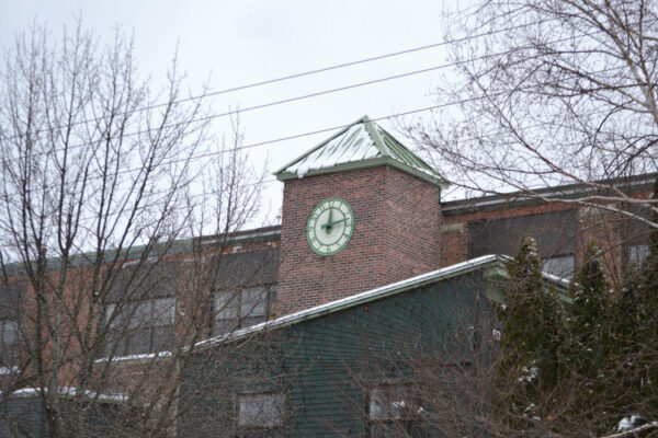
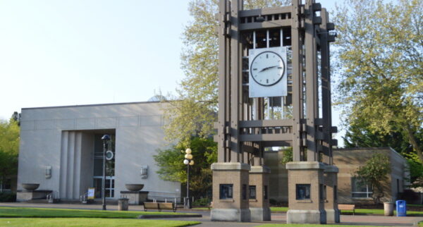
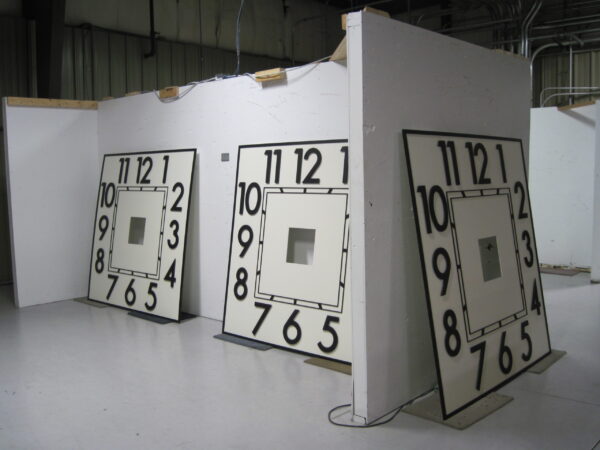
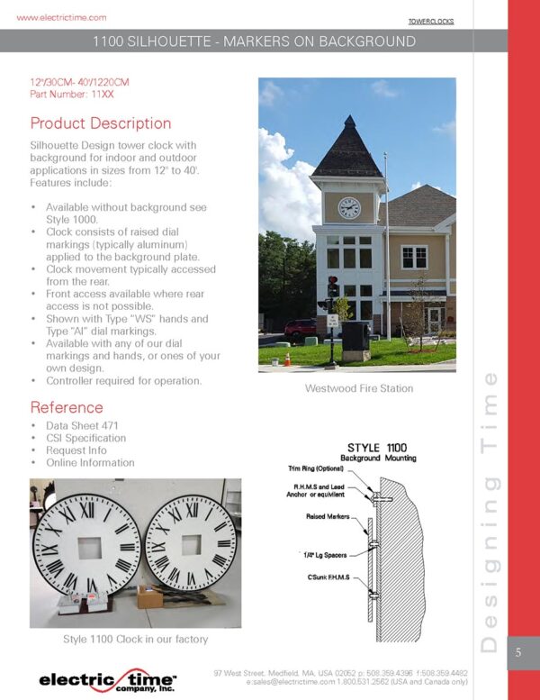
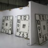
Silhouette Design tower clock with background for indoor and outdoor applications in sizes from 12″ to 20′. Features include:
- Available without background see Style 1000.
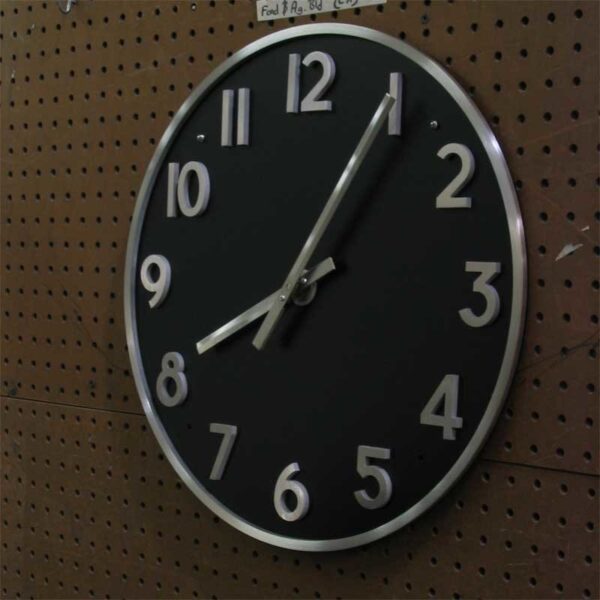
- Clock consists of raised dial markings (typically aluminum) applied to a background.
- Clock movement typically accessed from the rear
- Front access available where rear access is not available.
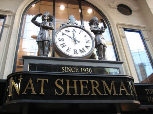
- Shown with Type “WS” hands and Type “AI1” dial markings.
- Available with any of our dial markings and hands, or ones of your own design.
99B Control required for operation.
Additional information available in the documentation tab above.
Tower Clock Movement Mounting Options
CSI Specifications
107413 Specifications
PART 1 GENERAL
1.01 Section Includes
A. Tower Clock Components and Remote Control System.
B. Related Sections
– Basic Materials and Methods: All raceways, junction boxes, and conduit wire to be provided by electrical contractor.
PART 2 PRODUCTS
2.01 CLOCKS
A. Furnish complete clock system consisting of (N) tower clocks and (1) remote control system.
“N” is the quantity of clocks required.
B. Manufacturer: Electric Time Company, Inc., 97 West Street, Medfield, MA, USA (508)-359-4396/(800)-531-2562 FAX (508)-359-4482 – http://www.electricitme.com – sales@electrictime.com
C. Tower Clock Components
Dial: Aluminum.
Finishes: Dial markings, trim ring and hands to have a black polyurethane finish. Background to have an off-white painted finish. Other standard colors available which are: medium or dark bronze (matches Duranodic #312 & #313), off-white, bright white, matte-black, satin aluminum, forest green, red or gold.
Hands:“HH” design. “HH” is the design of clock hands, please specify
Dial Markings: “FF” design. “FF” is the design of clock dial markings, please specify
Movement: Style MI Design. 24VAC drive motor and electronics. 8 second maximum run time. Alternating hall effect switched closed loop minute impulse operation. Composite lubrication free bearings. Single source: Clock and movement to be manufactured by the same company.
Ring: Aluminum trim ring.
Style: Style WP-11XX Design
“XX” is the size of clock – available standard sizes are 12”, 15”,18”, 24”, 30”, 36”, 42”, 48”, 54”, 60” 72”, 84” and 96”
D. Provide Type 99B-MI automatic reset control;
– IP65 Enclosure – Indoor & Outdoor Use
– Automatically resets clock after power failures.
– Automatically resets clocks for daylight savings time (if required)
– Precision Quartz Time base 4 minutes per year maximum drift.
– Optional GPS – no drift.
– Built in 100 year daylight savings time calendar.
– 2 Line 16 character backlighted LCD display.
– ETL listed to UL 863.
– Power Failure Event logging.
– Standard MI output – 4 clocks maximum standard
– Standard 24VDC RP output -20 clocks maximum
– Sweep Second hand output
– Hour Strike Capability.
– RS-232 and RS-485 output ports
– 24 VAC hour strike output – configurable pulse output
PART 3 EXECUTION
3.01 Installation
A. Inspect substrates, supporting items and related conditions, to ensure that they are ready to receive each item, prior to commencement of installation.
B. Install each item at locations indicated on drawings, as detailed, and in accordance with manufacturers’ instructions.